Distributed Virtual Routing (DVR) with Neutron
Distributed Virtual Routing (DVR) is one of the two methods of deploying Openstack Neutron. When using deploying your cloud, figuring out if you will need to setup Distributed Layer 3 (L3 ) vs centralized L3 control is important. DVR can be described as below:
- Distributed Layer 3 (L3) space across all compute hosts. No concept of network node.
- Requires dedicated node/nodes for L3 Source Network Address Translation (SNAT).
- North-South and East-West traffic is handled at each compute host.
All deployments come with its own set of advantages & disadvantages. Some advantages of using the DVR mode:
- High performance (L3 at compute node)
- Single hop Floating IP (FIP) i.e. North-South traffic
- East-West traffic also is routed at source.
- Failure domain reduced to a single compute node.
- Great load sharing in terms of L3 routing & DHCP servers.
- Easier for maintenance when it comes to re-purposing the otherwise central network node.
Some reasons for why DVR sometimes isn’t a good fit:
- Difficult to debug (Platform9 solves this for you).
- Needs external network for all compute nodes.
- Exhausts 1 additional FIP per compute node.
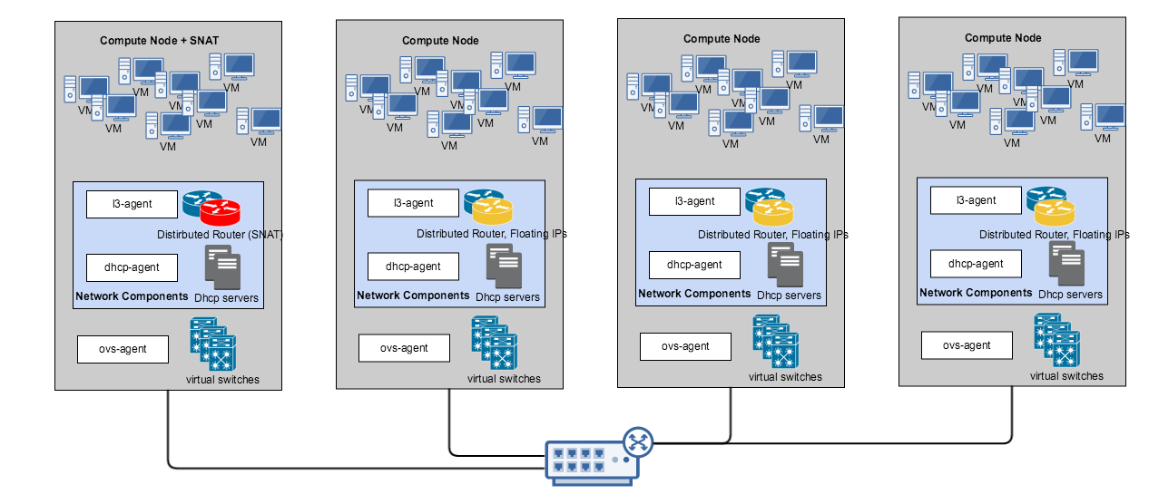
Components in a DVR deployment are distributed as shown below:

The Network components in the above picture consist of the dhcp-agent and the l3-agent. DHCP agent is responsible for managing DHCP servers for tenant networks along with DNS service while the L3 agent is responsible for routing i.e. cross networks both east-west and north-south traffic. You can assign one or more nodes to run SNAT. VM’s without Floating IPs will connect external to the cloud through this SNAT service node. VMs with floating IPs however will directly communicate external to the cloud from the host/server it is running in.
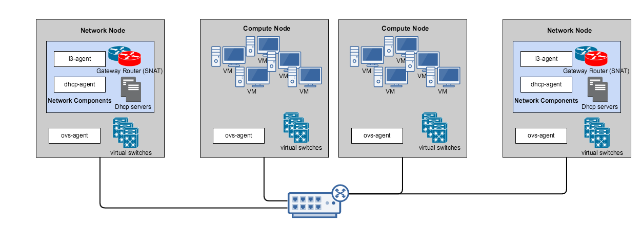
In comparison, components in a non-DVR deployment is architect-ed as below:

One or more network nodes are dedicated to run the network services. Compute nodes primarily run compute workloads. All cross network traffic (east-west & north-south) will be routed by the routers present in the network node. For example if two VMs on the same server but on different networks (192.168.1.0/24 and 192.168.2.0/24) need to talk to each other, they would need to go through one of the network nodes. In case of DVR, this routing will take place on the same server.
A condensed side-by-side comparison of the two architectures/setups is given below.
| Feature | Centralized Routing based L3 (Non-DVR) | Distributed Virtual Routing based L3 | |
|---|---|---|---|
| DHCP server | setup | On network node. Redundancy limited to number of network nodes. | On any hypervisor. User has the control to choose which hypervisors host DHCP servers. This is scalable to 'N' where N is the number of hypervisors |
| Failure Domain | Active-Active if no. of network nodes > 1 | Active-Active | |
| Failover | Moves to other network node if network node > 2. | Moves to another hypervisor/node with dhcp service enabled if they are > 2 | |
| L3 (IP Routing) | setup | On network node only. No active-active redundancy. | On all hypervisors for East West traffic and on SNAT enabled hypervisors for North South traffic. |
| SNAT | On a particular network node. Load balanced if network node > 2 | On a particular hypervisor. Load balanced to the hypervisors enabled with SNAT | |
| Floating / Elastic IPs | On the same network node as SNAT | On the specific hypervisor where VM runs. | |
| North-South traffic flow | Through network node. Both SNAT & FIP | SNAT through SNAT hypervisor but when using FIP, directly through hypervisor running the VM. | |
| East-West traffic flow | Through network node. | Directly at hypervisor. | |
| redundancy | active-active possible (In our roadmap) | Active-Active only makes sense for SNAT. (In our roadmap) | |
| Failure-domain | Loss of L3 connectivity till failover. | Loss of hypervisor alone. If hypervisor running SNAT, loss of SNAT till failover. | |
| Failover | L3 routers (SNAT & FIP) failover to to other routers if network_nodes > 1 after timeout. | SNAT router failover to other hypervisor after timeout. | |
| IP usage | external IP's | 1 for external n/w gateway interface per L3 virtual router. 1 each for FIP | 1 for external n/w gateway interface per L3 virtual router (snat), 1 each for FIP gateway/namespace (=no. of hypervisors) + 1 FIP per VM. |
| Internal IPs | 1 per tenant network per router | 2 per tenant network per router ( 1 for SNAT/ 1 for Gateway) | |
| Advantages | External network connectivity not required on all nodes. Easier to debug. Especially North-South Traffic. Solves DMZ type use cases. Easier for Maintenance and network node provision planning. (1 per rack, 1 per multiple racks etc) Other SDN solutions use a similar approach. (Gateway nodes for N-S traffic). | High performance (L3 at hypervisor) Single hop FIP (North-South traffic) East-West traffic also is routed at source. Failure domain reduced to a single hypervisor node. Better load sharing in terms of L3 routing & DHCP servers. Will be easier for maintenance & network provisioning since you can choose which role (SNAT/DHCP) goes to which server giving you the control to architect & plan downtime. |
|
| Disadvantages | Single point of failure till active-active feature (In the roadmap) Throughput bottleneck for ALL l3 traffic. Not viable for network intensive workloads | Very difficult to debug. Needs external network for all hypervisor nodes. Exhausts 1 additional fip per hypervisor. |