Neutron prerequisites for CentOS
This OpenStack tutorial describes prerequisites to prepare your servers to leverage OpenStack Neutron with CentOS Linux/KVM.
For a general description of Neutron networking concepts, refer to this Tutorial: Networking with OpenStack Neutron Basic Concepts
Note: Refer to this Tutorial for hardware requirements for Platform9 Managed OpenStack.
Prepare Your Linux/KVM Physical Servers for Neutron
The following image represents three hypervisors connected in a Managed OpenStack Neutron network.
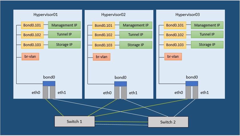
Figure 1. Neutron Network Configuration Example
In order to run a Managed OpenStack Neutron network, each of your physical hypervisors and the Neutron network nodes must be prepared with following steps.
Note: There are no separate network nodes in a Distributed Virtual Routing (DVR) network.
Step 1: Install, Enable, & Start the NTP Daemon.
The NTP daemon is required for all components to have their time synchronized.
Run the following commands to install, enable and start the NTP daemon.
[bash]yum install -y ntp
systemctl enable ntpd
systemctl start ntpd[/bash]
Step 2: Set SELinux to permissive
This is required for Open vSwitch (OVS) to be able to manage networking.
Run the following commands to set SELinux to permissive.
[bash]sed -i s/SELINUX=enforcing/SELINUX=permissive/g /etc/selinux/configsetenforce 0[/bash]
Step 3: Disable Firewalld and NetworkManager
This is required for KVM and OVS to be able to create iptables rules directly without firewalld getting in the way.
Run the following commands to disable firewalld and NetworkManager.
[bash]systemctl disable firewalldsystemctl stop firewalld
systemctl disable NetworkManager
systemctl stop NetworkManager[/bash]
Step 4: Enable Network
Run the following command to enable network.
[bash]systemctl enable network[/bash]
Step 5: Load the modules needed for Neutron
Run the following commands to load the modules needed for Neutron.
[bash]modprobe bridge
modprobe 8021q
modprobe bonding
modprobe tun
echo bridge > /etc/modules-load.d/pf9.conf
echo 8021q >> /etc/modules-load.d/pf9.conf
echo bonding >> /etc/modules-load.d/pf9.conf
echo tun >> /etc/modules-load.d/pf9.conf[/bash]
Step 6: Add sysctl options
Run the following commands to add sysctl options.
[bash]echo net.ipv4.conf.all.rp_filter=0 >> /etc/sysctl.conf
echo net.ipv4.conf.default.rp_filter=0 >> /etc/sysctl.conf
echo net.bridge.bridge-nf-call-iptables=1 >> /etc/sysctl.conf
echo net.ipv4.ip_forward=1 >> /etc/sysctl.conf
echo net.ipv4.tcp_mtu_probing=1 >> /etc/sysctl.conf
sysctl -p[/bash]
Step 7: Add the Platform9 YUM Repo
Run the following command to install the Platform9 YUM repository.
[bash]yum -y install https://s3-us-west-1.amazonaws.com/platform9-neutron/noarch/platform9-neutron-repo-1-0.noarch.rpm[/bash]
Step 8: Install Open vSwitch
Run the following command to install Open vSwitch.
[bash]yum -y install –disablerepo=”*” –enablerepo=”platform9-neutron-el7-repo” openvswitch[/bash]
Step 9: Enable and start Open vSwitch
Run the following commands to enable and start Open vSwitch.
[bash]systemctl enable openvswitch
systemctl start openvswitch[/bash]
Step 10: Configure physical interfaces
Note: Figure 1 in the article represents a sample Neutron network configuration. Steps 10 through 14 are based on the configuration shown in Figure 1 from the article. Steps 10 through 14 describe the configuration of physical interfaces into a Linux bond, addition of VLAN interfaces for management, VXLAN/GRE network traffic and storage. You may or may not require one or more of these steps. The steps to follow would be based on your Neutron network configuration. For instance, if you do not plan on using VXLAN/GRE, you can skip the step to set up VXLAN/GRE tunneling interface.
We assume the interface names to be eth0 and eth1.
Substitute eth0 and eth1 with the appropriate interface names per your setup, when you run the commands given for this step.
Similarly, we are assuming an MTU of 9000 (VXLAN requires an MTU of at least 1600)
Make sure all physical switches are configured to handle the MTU of 1600 or you might have problems.
Run the following commands to configure physical interfaces.
/etc/sysconfig/network-scripts/ifcfg-eth0
[code linenum=”false”]DEVICE=eth0
ONBOOT=yes
BOOTPROTO=none
MTU=9000
MASTER=bond0
SLAVE=yes[/code]
/etc/sysconfig/network-scripts/ifcfg-eth1
[code linenum=”false”]DEVICE=eth1
ONBOOT=yes
BOOTPROTO=none
MTU=9000
MASTER=bond0
SLAVE=yes[/code]
Step 11: Set up the Bond interface
Note: We are assuming bonding type=4 (LACP) refer to CentOS Bonding Types to learn more.
Run the following commands to set up the bond interface.
/etc/sysconfig/network-scripts/ifcfg-bond0
[code linenum=”false”]DEVICE=bond0
ONBOOT=yes
BONDING_MASTER=yes
BONDING_OPTS=”mode=4″
MTU=9000[/code]
Step 12: Setup the Management interface
Note: We are assuming VLAN 101 for the Management network. Replace it with the correct VLAN ID per your setup.
We are assuming subnet 192.0.2.0/24 for Management. Replace it with the correct subnet per your setup.
/etc/sysconfig/network-scripts/ifcfg-bond0.101
[code linenum=”false”]DEVICE=bond0.101
ONBOOT=yes
BOOTPROTO=none
TYPE=Vlan
VLAN=yes
IPADDR=192.0.2.10
NETMASK=255.255.255.0
GATEWAY=192.0.2.1
DNS1=192.0.2.100
DNS2=192.0.2.200[/code]
Step 13: Setup the VXLAN/GRE tunneling interface (Optional)
Note: We are assuming VLAN 102 for VXLAN/GRE tunneling. Please use the correct VLAN per your setup.
We are assuming subnet 198.51.100.0/24 for VXLAN/GRE tunneling. Please use the correct subnet per your setup.
Run the following commands to VXLAN/GRE tunneling interface.
/etc/sysconfig/network-scripts/ifcfg-bond0.102
[code linenum=”false”]DEVICE=bond0.102
ONBOOT=yes
BOOTPROTO=none
TYPE=Vlan
VLAN=yes
IPADDR=198.51.100.10
NETMASK=255.255.255.0[/code]
Step 14: Setup the Storage interface (Optional)
Note: We are assuming VLAN 103 for the storage network. Replace it with the VLAN per your setup.
We are assuming subnet 203.0.113.0/24 for the storage network. Replace it with the subnet per your setup.
Run the following commands to set up the storage interface.
/etc/sysconfig/network-scripts/ifcfg-bond0.103
[code linenum=”false”]DEVICE=bond0.103
ONBOOT=yes
BOOTPROTO=none
TYPE=Vlan
VLAN=yes
IPADDR=203.0.113.10
NETMASK=255.255.255.0[/code]
Step 15: Restart Networking
Warning: Make sure you have console access to your host. You will be disconnected if the configuration is incorrect.
Run the following command to restart the network service.
[bash]systemctl restart network.service[/bash]
Step 16: Create OVS Bridges
The number of OVS bridges you need will determine on how many physical networks your hosts connect to, and what types of networks you will be creating.
Let us look at some basic networking terminology before creating the bridges.
- An access port represents a single “flat” physical network or VLAN, and will carry untagged traffic.
- A trunk port logically groups together multiple VLANs. An 802.1Q “QTag” header will be inserted into the Ethernet frame for all VLAN traffic. All untagged traffic is implicitly assigned a default, native VLAN per your data center’s switch configuration.
Each physical network corresponds to a trunk or access port (an individual NIC, or a pair of NICs bonded together) on the host. An Open vSwitch bridge must be created for each physical network.
When configuring Platform9 OpenStack’s Networking Config, each physical network is given a Label as a name, and that label mapped to a particular OVS bridge on the host during host authorization.
Let us look at two different examples of common host networking setups.
Example 1: Non-DVR setup with one external flat network, and trunk port for VLAN traffic
The following figure represents a non-DVR network setup with an external flat network, and a trunk port for VLAN traffic.

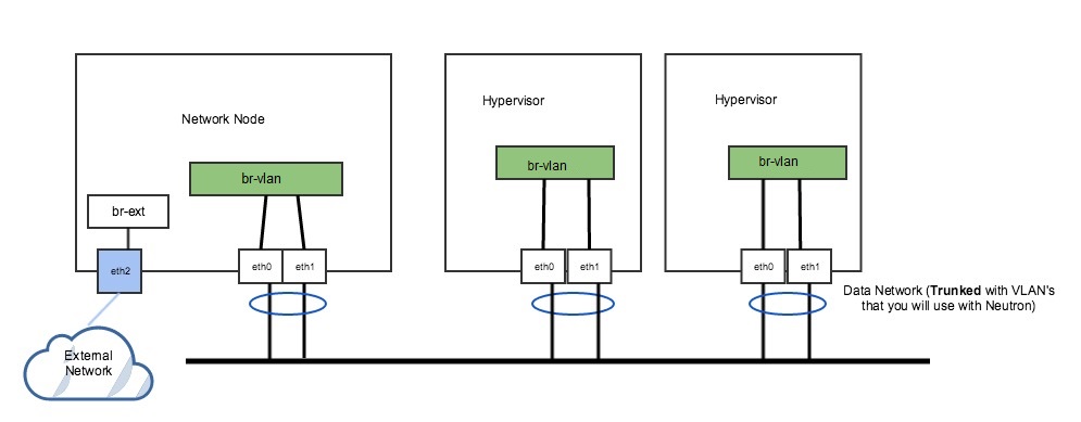
Figure 2. Non-DVR Network Setup
In Figure 2 above, the network has a trunk port consisting of eth0 and eth1 in a bond that will carry our VLAN based networks(tenant, provider), as well as a dedicated port (eth2) that connects to a separate external network. This is a legacy, non-DVR setup where external connectivity and L3 capability is only on network nodes. Nodes that are hypervisors only carry the tenant network traffic, and need just 1 OVS bridge.
Run the following commands to add OVS bridges on the hypervisors. The steps below assume eth0/eth1 have already been configured in a Linux bond called “bond0”. Please refer to steps 10-15 to set up your physical interfaces.
[bash]ovs-vsctl add-br br-vlan
ovs-vsctl add-port br-vlan bond0[/bash]
On our network node, we have a separate NIC that connects to a different physical network. For this, we need a separate OVS bridge.
Run the following commands to add an OVS bridge.
[bash]ovs-vsctl add-br br-ext
ovs-vsctl add-port br-ext eth2[/bash]
Example 2: DVR setup with a pair of NICs in a bond
The following figure represents a DVR network setup with a pair of NICs in a bond.
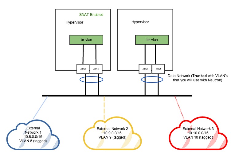
Figure 3. DVR Network Setup
In the DVR setup seen in figure 3 above, every host has external L3 connectivity. Here, we only have a pair of NICs in a bond. Therefore this OVS Bridge can only support one Flat (untagged) network, and as many VLAN-tagged networks as your networking infrastructure allows. There are multiple external networks that are VLAN-based, in addition to our tenant networks.
Run the following commands to add an OVS bridge on all hosts.
Note: The steps below assume eth0/eth1 have already been configured in a Linux bond called “bond0”. Please refer to steps 10-14 to set up your physical interfaces.
[bash]ovs-vsctl add-br br-vlanovs-vsctl add-port br-vlan bond0[/bash]