Overview & Architecture
Private Cloud Director offers full Software Defined Networking (SDN) as part of the offering. The Networking Service in Private Cloud Director offers a broad range of capabilities.
This document provides an overview of the Private Cloud Director Networking Service.
Overview
Private Cloud Director Networking Service is a full Software Defined Networking (SDN) service that gives administrators full flexibility to configure their private cloud networking based on their organization's security and networking policies.
The Networking Service offers a broad range of capabilities, including:
- Perform network segmentation using VLAN
- Create overlay networks using network encapsulation technologies like VXLAN or GRE.
- Create one or multiple private and / or public networks to support self-service network provisioning. Use them along with gateways, routers and public IP pools to fully support networking requirements for dev/test as well production networking use cases.
- Create granular security policies via the use of security groups and security rules to isolate traffic between virtual machines to achieve microsegmentation
- Provision infrastructure services such as load balancers or DNS as a service.
Concepts
Concepts we will use in this document:
Private Cloud Director Management Plane
This is the Private Cloud Director management plane installed locally when using Private Cloud Director self-hosted deployment. See Hosting Options for more information on various hosting options. If using, SaaS hosted deployment model, you can ignore this component in the diagrams below.
Physical Network Interface
In the context of a hypervisor, a network interface refers to a physical network interface, such as eth0, or a bonded network interface (e.g. bond0) that is bonded from multiple physical network interfaces.
Management Network
The network used to carry communications between hypervisor cluster control plane components and data plane components, and to ensure certain cluster level functions (such as host liveness detection).
VLAN
VLAN stands for Virtual Local Area Network. VLANs are logical networks that may operate within a single Physical Network. The network traffic on each VLAN is independent of and invisible to the network traffic on another VLAN on the same Physical Network.
VXLAN
VXLAN stands for Virtual Extensible Local Area Network. VXLAN is a virtual overlay network that is built on top of Open Systems Interconnection Model (OSI) Layer 2 and Layer 3 technology. VXLAN extends the virtual LAN (VLAN) address space.
VLAN supports the assignment of up to 4096 VLAN IDs at a time, which may be insufficient for big-scale cloud computing. VXLAN adds a 24-bit segment ID, and hence, increases the number of available VLAN IDs to 16 million.
GENEVE
GENEVE stands for Generic Network Virtualization Encapsulation and is a network encapsulation / tunneling technology that creates Layer-2 overlay networks over Layer-3 infrastructure, by encapsulating Layer-2 frames in UDP packets.
Following sections describe 3 sample networking architectures when deploying networking for Private Cloud Director.
Networking in Private Cloud Director
Networking in Private Cloud Director utilizes Open vSwitch (OVS) and Open Virtual Switch (OVN) under the hood to provide full Software-Defined Networking capabilities of out the box.
Open vSwitch (OVS)
Open vSwitch (OVS) is an open-source, high-performance virtual switch that acts as a software-based switch in a Private Cloud Director environment. Open vSwitch enables virtual machines to communicate with each other and with physical networks, and provides advanced features for network management and security.
Open Virtual Network (OVN)
OVN (Open Virtual Network) is an open-source network virtualization platform built on top of Open vSwitch (OVS). It extends OVS to provide advanced network abstractions such as logical switches, logical routers, and distributed firewalls to manage networking for virtualized and containerized environments.
An OVN logical network is a network implemented in software that is insulated from physical (and thus virtual) networks by tunnels or other encapsulations. This allows IP and other address spaces used in logical networks to overlap with those used on physical networks without causing conflicts.
Logical network topologies can be arranged without regard for the topologies of the physical networks on which they run. Thus, VMs that are part of a logical network can migrate from one physical machine to another without network disruption.
Sample Architectures
Architecture 1: Single Network Interface, Simple Networks
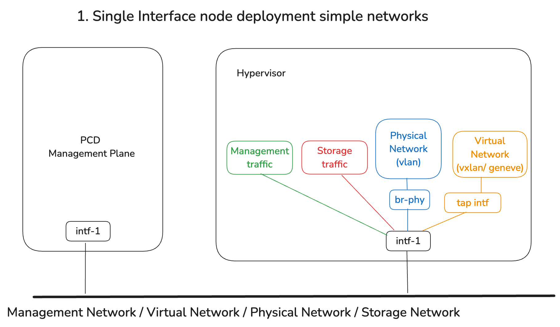
In this architecture, a single physical network interface (either single physical or a single bonded interface) is used to carry all network traffic on an existing physical network:
- The pre-requisite would be to prepare the network interface before configuring the virtualized cluster networking
- The underlying physical network traits, including its use of VLAN, or connectivity to external networks, can be configured to expose this existing physical network into the virtualized cluster
- Private Cloud Director can apply all following network changes, including creating a logical management network, a logical storage network, a logical tunnel network (using either VXLAN or Geneve as the underlay)
This is the simplest possible configuration, but is not recommended for production due to the lack of segregation between different traffic types.
Architecture 2: Multiple network interfaces, segregated simple networks
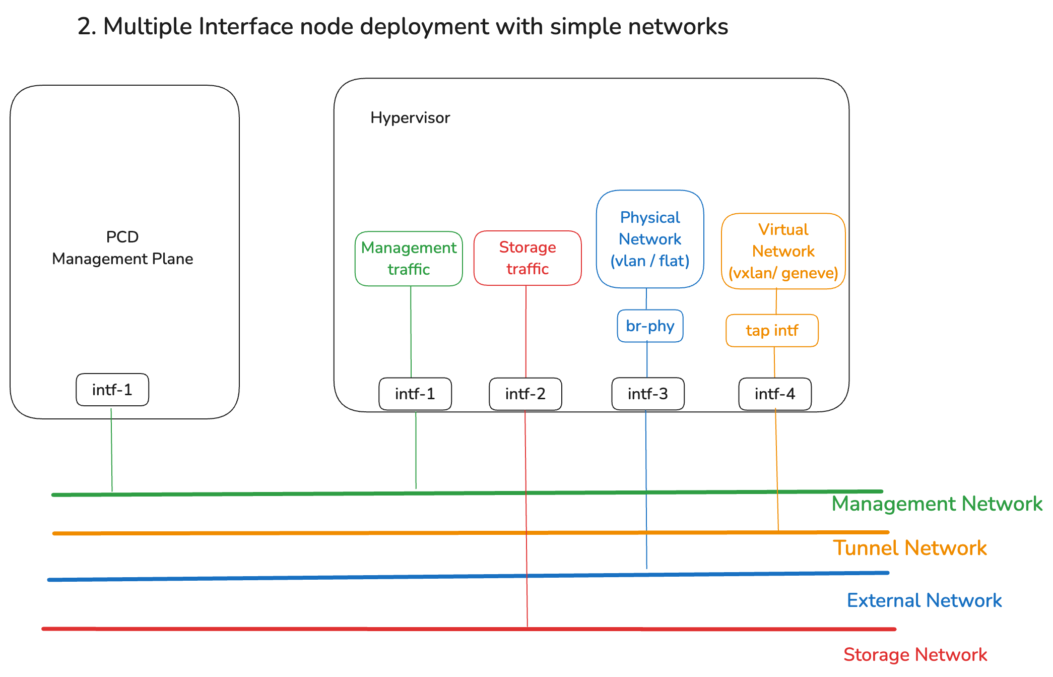
This is a common architecture, suitable for production usage. It features:
- Multiple physical or bonded network interfaces, which must be ready before configuring networking for the virtualized cluster
- Isolation and improved QoS is achieved by using separate interfaces for management network, tunnel networks (virtual networks), external network and storage network.
- All of these networks can be configured within Private Cloud Director
Architecture 3: Complex networks with in-cluster NFV firewall for external traffic
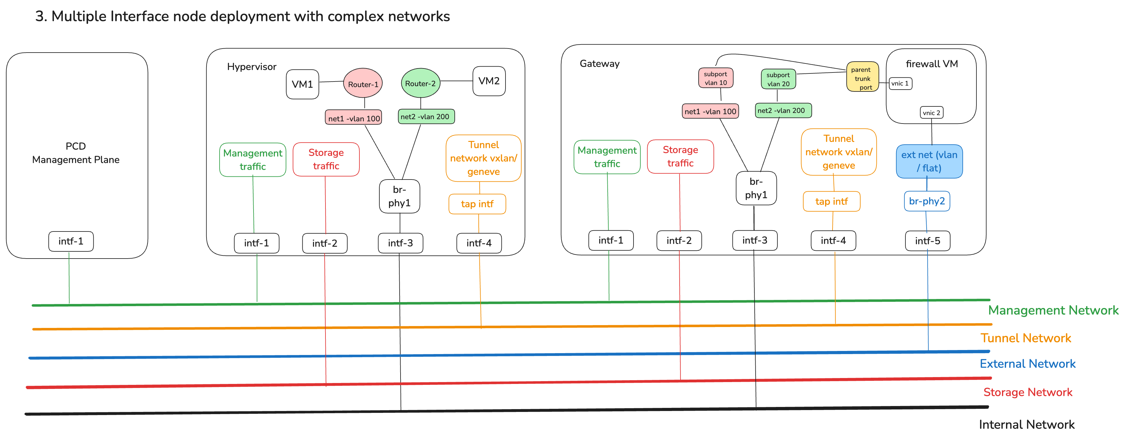
This is an advanced network architecture that uses networking constructs to enable an in-cluster firewall for your virtualized cluster that can filter all north-south traffic leaving the virtualized cluster onto an external network:
- Beyond preparing the network interfaces, in this architecture, a software firewall (NFV) VM is used to filter traffic
- The firewall VM is deployed onto a host that serves as the 'Gateway' out of the virtualized cluster. The firewall VM is connected via a special bridge to the external network. No other resources in the cluster can connect to this special bridge directly.
- All hosts in the virtualized cluster, including the gateway host, use a common bridge configuration (
br-phy1in this diagram), which enables the creation of multiple logical networks with connectivity to the firewall (and thereby external networks). In this diagram, net1 using vlan 100 and net2 using vlan 200 are two different physical networks that are used by workloads - Virtual routers are deployed to provide the appropriate level of connectivity across networks
- To ensure adequate throughput, the firewall VM uses trunk ports and multiple vNICs to support internal networks in the cluster that are used by VMs
- Management, storage and virtual networks are used within the cluster, but since these contain non outgoing traffic, they are not monitored by the firewall
Networking Service Configuration
Networking Service configuration is primarily performed while configuring your cluster blueprint. Then when you create one or more clusters and add hosts to them, you can apply portions of the networking configuration you specified in the blueprint to those hosts.
Following section provides details about ways to configure your Networking Service as part of cluster blueprint creation.
To describe your physical network architecture, you'll need to:
- Configure global network parameters
- Describe each physical network
Cluster Network Parameters
DNS Domain Name is used to ensure that when VMs are provisioned, DNS entries within the cluster reflect the FQDNs for the VMs that include this domain name. By default, clusters use an internal DNS resolution service, but can be configured to use an external DNS management service via a custom configuration.
By default, clusters use an internal DNS resolution service, but can be configured to use an external DNS management service via a custom configuration.
Enable Virtual Networks
To enable Virtual Networks, you'll need to configure the underlay technology that is used to tunnel virtual network traffic using an existing physical network. You can choose to use VLANs, VXLANs or Geneve as the underlay technology for virtual networks.
Within a cluster, you can only enable one underlay technology, and all hosts in that cluster will be configured automatically to use that underlay technology using the associated physical network interface. Any virtual networks that you create will be available to workloads running on all hosts in the cluster.
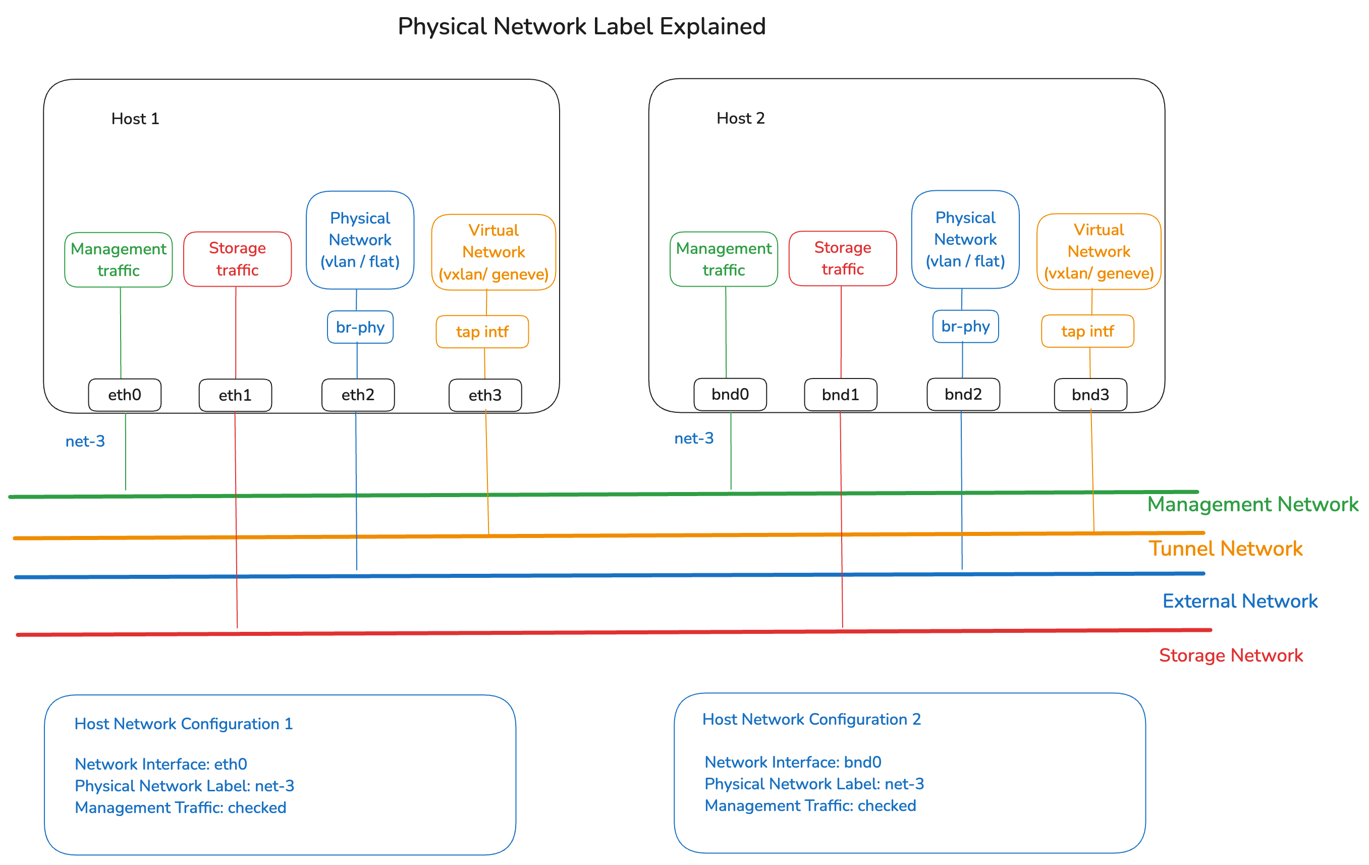
Host Network Configuration
A Host Network Configuration allows you to specify networking characteristics of a group of hosts. You do this by defining one or more Network Interfaces, assigning them a Physical Network Label, and describing what type of traffic will flow through these interfaces.
Once you create one or more Host Network Configurations as part of your cluster blueprint, you can then choose which configuration to apply to a host when you authorize a new host to be added to a specific virtualized cluster. This enables you to specify different networking configuration for different clusters or even different hosts within the same cluster.
Physical Network Label
A Physical Network Label gives a label to a physical interface on a host and allows you to direct Private Cloud Director to use network interfaces from different groups of hosts that may be named differently for the same physical network.
For example, say you have one set of hosts with interfaces named eth0, eth1 and eth2 and a second set of hosts with bonded interfaces with names bond0, bond1 and bond2. Now say you wish to use eth0 from first set of hosts and bond0 from second set of hosts for management traffic because they are both connected to the management network. You will do this by creating two separate Host Network Configurations, one for the first set of hosts and another for the second. But in both, you will provide the same Physical Network Label for eth0 and bond0, to indicate to Private Cloud Director that they belong to the same physical network even though they are named differently. You will then check the checkbox for 'management traffic' for this interface in both configurations.
Network Traffic Types
Following are the different types of network traffic you can specify for the interfaces
- Management - This is the management traffic interface that you typically use for administrative tasks like configuration, monitoring, and remote access for your hosts. This interface will also be used for communication between your SaaS or self-hosted management plane and hosts.
- VM console - This is the network interface that Private Cloud Director UI will use to load the virtual machine console via VNC using the hypervisor host's IP. In most setups, this will generally be same as your management traffic interface.
- Image library - This interface will be used for lmage library traffic. The UI will use this interface to upload any images that the user tries to upload via the UI. It will also be used to serve the image contents to the hypervisor when a vm is being provisioned using that image. This will also generally be same as your management traffic interface in most setups.
- Virtual network tunnels - This interface will be used behind the scenes to route traffic when new virtual networks get created.
- Host liveliness check - This interface will be used by the virtual machine high availability service to check if the hypervisor host is up or down.
Network Node Role
When you enable Distributed Virtual Routing, you do not need to assign Network Node role to any host when adding it to a cluster as the networking components are uniformly installed on each host when it gets added to a cluster. If you disable DVR, you will need to explicitly assign Network Node role to a host when adding to a cluster, so that the networking service components get installed on it.
Network Service Components
As part of host configuration for networking, two agents get installed on the host - ovn metadata agent and ovn controller agent. You can see more information about log files specific to these agents under the Log Files section.
Debugging Networking Service Issues
If the Networking Service appears Unhealthy in the Private Cloud Director Service Health page, this likely means that the networking service components running on one or more hosts are experiencing an issue. Reference the Networking Service Log Files to identify the specific error.
Log Files
The Networking Service component log files are located at:
/var/log/pf9/pf9-neutron-ovn-metadata-agent.log
/var/log/ovn/ovn-controller.log