Preparing Ubuntu Server
This article describes how prepare a Ubuntu server to be added as a host to Platform9 Managed OpenStack (PMO) private cloud.
For a description of PMO networking concepts, refer to the Networking Basic Concepts tutorial. Refer to PMO prerequisites for Linux/KVM for systems requirements and supported Ubuntu Operating System versions.
Supported Operating System Version
Platform9 Managed OpenStack supports Ubuntu LTS 18.04 (64-bit) and Ubuntu LTS 20.04.
Ubuntu 16.04 is now deprecated and will not be supported with the next (5.3) release of Platform9 Managed OpenStack.
Step 1 - Install Ubuntu Operating System
Make sure that your Ubuntu server is configured appropriately with access to storage and physical networking. Download and install Ubuntu on your physical server. You can download Ubuntu distributions from here: http://releases.ubuntu.com.
We recommend installing the minimal Ubuntu operating system. Platform9 agents are prepared to pull in any required package dependencies and get them installed on your server to prepare it to be part of PMO. This includes any libvirt/KVM package dependencies.
Step 2 - Ensure Virtualization is Enabled
Ensure that virtualization is enabled for your server by checking your server’s BIOS settings. If disabled, enable virtualization for the server to be able to act as a hypervisor within PMO.
Step 3 - Ensure the System Clock is Synchronized
Your host will fail to authenticate with PMO services if its date time settings are incorrect. Type ‘date’ on the server command prompt to verify that the current date and time are correct. If they aren’t, then one possible fix is to enable the network time protocol (NTP) daemon service:
sudo apt-get install ntpservice ntp startThe following image (Figure 1) represents three hypervisors connected in a Managed OpenStack Neutron network.
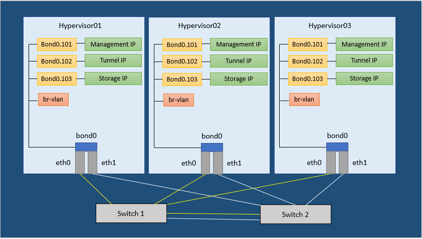
In order to run a Managed OpenStack Neutron network, each of your physical hypervisors and the Neutron network nodes must be prepared with following steps.
There are no separate network nodes in a Distributed Virtual Routing (DVR) network.
Step 4 - Install Required Packages
Ubuntu Cloud Archive (UCA) gives users the ability to install newer releases of libvirt and qemu-kvm packages. Refer https://wiki.ubuntu.com/OpenStack/CloudArchive for details. Run following command to enable UCA on your Ubuntu server:
sudo add-apt-repository cloud-archive:queensIt’s usually a good practice to get your system up to date with latest patches and updates. Run the following command to do this:
sudo apt-get updateRun the following commands to load the modules needed for Neutron.
apt-get install -y dnsmasq arping conntrack ifenslave vlan software-properties-commonmodprobe bridgemodprobe br_netfiltermodprobe 8021qmodprobe bondingecho bridge >/etc/modules-load.d/pf9.confecho 8021q >> /etc/modules-load.d/pf9.confecho bonding >> /etc/modules-load.d/pf9.confecho br_netfilter >> /etc/modules-load.d/pf9.confStep 5 - Add sysctl options
Run the following commands to add sysctl options.
echo net.ipv4.conf.all.rp_filter=0 >> /etc/sysctl.confecho net.ipv4.conf.default.rp_filter=0 >> /etc/sysctl.confecho net.bridge.bridge-nf-call-iptables=1 >> /etc/sysctl.confecho net.ipv4.ip_forward=1 >> /etc/sysctl.confecho net.ipv4.tcp_mtu_probing=2 >> /etc/sysctl.confsysctl -pStep 6 - Add the Platform9 APT Repository
Run the following command to install the Platform9 APT repository that contains the latest Open vSwitch version.
wget -q -O - https://platform9-neutron.s3-us-west-1.amazonaws.com/ubuntu_latest/key.gpg | sudo apt-key add -add-apt-repository 'deb http://platform9-neutron.s3-website-us-west-1.amazonaws.com/ubuntu_latest /'Step 7 - Install Open vSwitch
If you wish to install an available older version, run the following command.
#Ubuntu 16.04 and higherapt-get install -y libopenvswitch=<version> openvswitch-common=<version> openvswitch-switch=<version>Alternatively, if you wish to install the latest version, run the following command.
# Ubuntu 16.04 and higherapt-get -y install openvswitch-switchStep 8 - Enable and start Open vSwitch
Run the following commands to enable and start Open vSwitch.
# Ubuntu 16.04 and highersystemctl enable openvswitch-switch.servicesystemctl start openvswitch-switch.serviceStep 9 - Install Router Advertisement Daemon
Run the following command to install the Router Advertisement Daemon.
apt-get -y install radvdStep 10 - Configure Physical Interfaces
Figure 1 in the article represents a sample Neutron network configuration. Steps 7 through 11 are based on the configuration shown in Figure 1 from the article. Steps 7 through 11 describe the configuration of physical interfaces into a Linux bond, addition of VLAN interfaces for management, VXLAN/GRE network traffic and storage. You may or may not require one or more of these steps. The steps to follow would be based on your Neutron network configuration. For instance, if you do not plan on using VXLAN/GRE, you can skip the step to set up VXLAN/GRE tunneling interface.
The article assumes the interface names to be eth0 and eth1. Substitute eth0 and eth1 with the appropriate interface names per your configuration when you run the commands given for this step. Similarly, the article assumes an MTU of 9000 throughout the data center (VXLAN requires an MTU of at least 1600). Ensure all physical switches are configured to handle the MTU configured on your servers.
Add the following to /etc/network/interfaces.
auto eth0 iface eth0 inet manual bond-master bond0 auto eth1 iface eth1 inet manual bond-master bond0 auto bond0 iface bond0 inet manual bond-mode 802.3ad bond-lacp-rate 1 bond-slaves eth0 eth1Step 11 - Set up the Bond interface
The article assumes bonding type 802.3ad (LACP). Refer to Ubuntu’s Ethernet Bonding modes to learn more.
Add the following to /etc/network/interfaces to create the bond.
auto bond0iface bond0 inet manualbond-mode 802.3adbond-slaves eth0 eth1Step 12 - Setup the Management interface
The article assumes VLAN 101 as the management network. Replace it with the appropriate VLAN ID per your configuration. The article assumes 192.0.2.0/24 as the management subnet. Replace it with the appropriate subnet per your configuration.
Add the following entries to the respective configuration file associated with the management VLAN, to set up the management interface.
auto bond0.101 iface bond0.101 inet static address 192.0.2.10 netmask 255.255.255.0 dns-nameservers 192.0.2.100 192.0.2.200 dns-search pf9.exampleStep 13 - Setup the VXLAN/GRE tunneling interface (Optional)
GRE and VXLAN require 24 bytes and 50 bytes of overhead, respectively. Platform9 recommends at least a minimum MTU of 1600 to accommodate this overhead, with a 9000 byte MTU preferred.
The article assumes VLAN 102 for VXLAN/GRE tunneling. Replace it with the appropriate VLAN per your configuration. The article assumes subnet 198.51.100.0/24 for VXLAN/GRE tunneling. Replace it with the appropriate subnet per your configuration.
Add the following entries to the respective configuration file associated with the tunneling VLAN, to set up VXLAN/GRE tunneling interface.
auto bond0.102iface bond0.102 inet staticaddress 198.51.100.10netmask 255.255.255.0post-up ifconfig bond0 mtu 9000post-up ifconfig bond0.102 mtu 9000Step 14 - Setup the Storage interface (Optional)
The article assumes VLAN 103 as the storage network. Replace it with the appropriate VLAN per your configuration. The article assumes 203.0.113.0/24 as the storage network. Replace it with the appropriate subnet per your configuration.
Add the following entries to the respective configuration file associated with the storage VLAN, to set up the storage interface.
auto bond0.103iface bond0.103 inet manualaddress 203.0.113.10netmask 255.255.255.0post-up ifconfig bond0 mtu 9000post-up ifconfig bond0.103 mtu 9000Step 15 - Restart Networking
Make sure you have console access to your host. You will be disconnected if the configuration is incorrect.
Run the following command to restart the network service.
ifdown -a ifup -a ifup -a --allow=ovsStep 16 - Create OVS Bridges
The number of OVS bridges you would need depend on how many physical networks your hosts connect to, and what types of networks you would create.
Let us look at some basic networking terminology before creating the bridges.
- An access port represents a single “flat” physical network or VLAN, and carries untagged traffic.
- A trunk port logically groups together multiple VLANs. An 802.1Q “QTag” header is inserted into the Ethernet frame for all VLAN traffic. All untagged traffic is implicitly assigned a default, native VLAN per your data center’s switch configuration.
Each physical network corresponds to a trunk or access port (an individual NIC, or a pair of NICs bonded together) on the host. An Open vSwitch bridge must be created for each physical network.
When configuring Platform9 OpenStack’s Networking Config, each physical network is given a Label as a name, and that label mapped to a particular OVS bridge on the host during host authorization.
Let us look at two different examples of common host networking setups.
Example 1: Non-DVR setup with one external flat network, and trunk port for VLAN traffic
The following figure (Figure 2) represents a non-DVR network setup with an external flat network, and a trunk port for VLAN traffic.
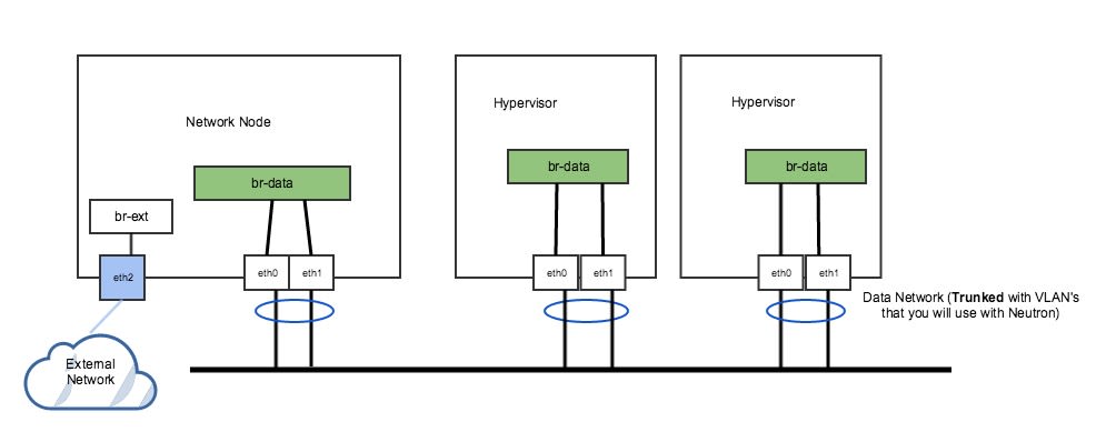
In Figure 2 above, the network has a trunk port consisting of eth0 and eth1 in a bond that will carry our VLAN-based networks (tenant, provider), as well as a dedicated port (eth2) that connects to a separate external network. This is a legacy, non-DVR setup where external connectivity and L3 capability is only on network nodes. Nodes that are hypervisors only carry the tenant network traffic, and need just 1 OVS bridge.
Run the following commands to add OVS bridges on the hypervisors. The steps below assume eth0/eth1 have already been configured in a Linux bond called “bond0”. Please refer to steps 7-11 to set up your physical interfaces.
ovs-vsctl add-br br-vlanovs-vsctl add-port br-vlan bond0On the network node, we have a separate NIC that connects to a different physical network. For this, we need a separate OVS bridge.
Run the following commands to add an OVS bridge.
ovs-vsctl add-br br-extovs-vsctl add-port br-ext eth2Example 2: DVR setup with a pair of NICs in a bond
The following figure (Figure 3) represents a DVR network setup with a pair of NICs in a bond.
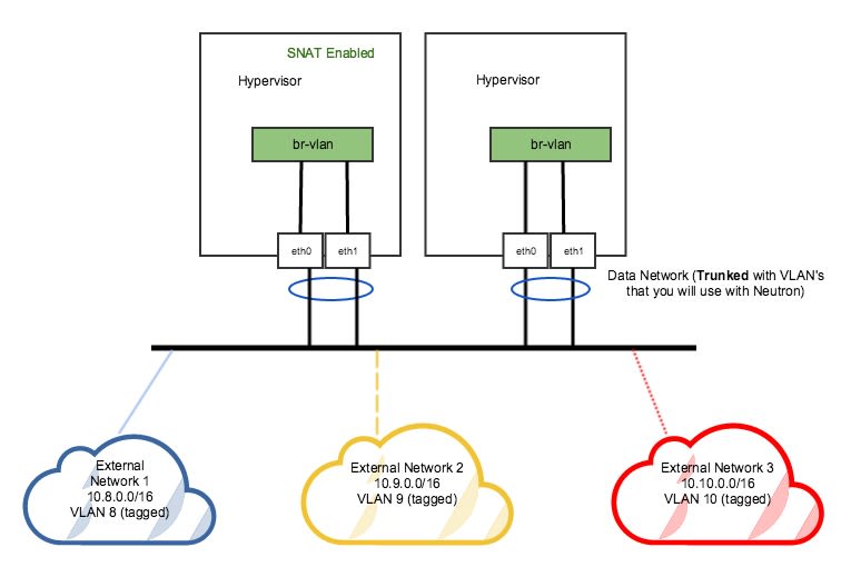
In the DVR setup seen in figure 3 above, every host has external L3 connectivity. Here, we only have a pair of NICs in a bond. Therefore, the OVS Bridge can only support one Flat (untagged) network, and as many VLAN-tagged networks as your networking infrastructure allows. There are multiple external networks that are VLAN-based, in addition to our tenant networks.
Run the following commands to add an OVS bridge on all hosts.
The steps below assume eth0/eth1 have already been configured in a Linux bond called “bond0”. Please refer to steps 7-10 to set up your physical interfaces.
ovs-vsctl add-br br-vlan ovs-vsctl add-port br-vlan bond0At this point, your Ubuntu server is properly configured and ready to be added as a hypervisor in your PMO cloud.
On authorizing hypervisor role on a host with custom instances path, you might encounter libvirt errors when performing some instance operations. Platform9 simplifies this by adding the configured instances_path to apparmor profile when hypervisor role is authorized, however more changes may be required based on your current profiles. Disabling AppArmor helps with this problem (https://help.ubuntu.com/community/AppArmor).